
In this experiment, we will discover quantum entanglement and how it can be generated. Entanglement means that one or more properties of two particles are correlated in a way that cannot be explained by classical physics.
A tempting analogy: imagine two marbles, one blue and one red. One is given to Alice, the other to Bob. When Alice sees her marble's color, she instantly knows Bob's. We might call their colors "correlated." However, this classical analogy is misleading — the marbles had definite colors all along; Alice simply learned which one she had. Quantum entanglement is fundamentally different: the photons do not have definite polarizations until measured. The measurement itself determines the outcome, and Bell's theorem proves that no classical "hidden color" explanation can account for the observed correlations.
This experiment may seem to break the laws of physics. It took many years to understand entanglement, but rest assured: entanglement does not allow information to travel faster than the speed of light, nor can it be used to change the past. The reason is subtle but important: each individual measurement yields a random outcome that the observer cannot control. The correlations only become visible when the two observers compare their results — and that comparison requires ordinary communication, limited by the speed of light.
To create entanglement, we use two thin nonlinear crystals called BBO (beta barium borate). Through a process known as Spontaneous Parametric Down-Conversion (SPDC), a single high-energy photon from the laser is converted into two lower-energy photons whose polarizations are entangled. The two photons are emitted at symmetric angles from the BBO. We place a rotatable polarizer in each path and count coincident detections — events where both detectors register a photon simultaneously.
The BBO produces photon pairs with parallel polarizations: if one is vertical, so is the other. Experiment with the animation to understand why the coincidence rate increases or decreases with different combinations of polarizer angles. The polarizers can be rotated using the pink handles. The presets highlight the most instructive angle combinations.
Curious about what an optical entanglement setup looks like? Here are a few pictures of our apparatus:
.png)


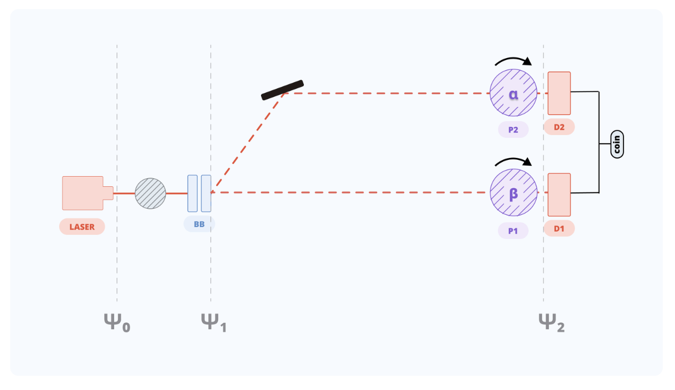
Here is a schematic representation of the setup. All equipment is shown, albeit not at scale.
.png)
The setup begins in the top right corner with a laser emitting at 404~nm. Before reaching a polarizing beam splitter, the beam passes through a half-wave plate to control its polarization and intensity. The beam splitter transmits only vertically polarized light; the horizontal component is directed to a beam dump.
The beam then passes through a pair of collimating lenses, which reduce the beam diameter and ensure it remains parallel. A set of two mirrors redirects the beam (a U-turn was necessary due to limited space on the optical table). A third lens focuses the beam onto the BBO crystal, ensuring all photon pairs are generated at the same location.
Before reaching the BBO, the beam's polarization must be set to 45° with zero relative phase between components. This is achieved using a half-wave plate and a Berek compensator, an optical device that finely adjusts the phase difference between the horizontal and vertical polarization components.
Both output paths (1 and 2) contain a focusing lens and a rotatable polarizer in front of the detector. The polarizers are rotated by motorized stages.
The final component (not shown in the diagram) is the coincidence counting system. The detectors are single-photon avalanche diodes (SPADs). Each detector is coupled to an optical fiber via a collimator and bandpass filter. The electronics record the number of photons detected within a specified time window and, crucially, the number of coincidences — simultaneous detections at both D1 and D2 within a narrow time gate (typically a few nanoseconds).
You can download all our data here:
The data file contains five columns. The first two are the polarizer angles, ranging from $-90°$ to $90°$. The remaining three columns are detector counts: D1 singles, D2 singles, and D1–D2 coincidences. All counts were recorded in one-second acquisition windows.
On the left is the data measured in the lab; on the right is the theoretical prediction. The two plots look quite different, but the key features remain. When both polarizers are set to the same angle, coincidence counts reach a maximum. When the polarizers are rotated 90° relative to each other, the counts drop to nearly zero.
Ideally, this pattern indicates the creation of a parallel Bell state: an entangled state in which the two photons always share the same polarization. (Bell states are explained in detail in the theory section.)
The experimental plot, however, is less clean than the theory predicts. The pump laser was likely not perfectly prepared before generating the entangled pairs, producing an imbalance in the state. The graph clearly shows many more vertically polarized pairs than horizontally polarized ones. This imbalance will appear in later experiments as well, but at least its origin is now understood.


Let us analyze these graphs. As noted above, there is a significant discrepancy between the theoretical prediction and the experimental data, though this does not fundamentally affect the conclusions. The key pattern remains: when the polarizer angles are parallel, coincidence counts are high; when perpendicular, they drop to nearly zero. The main deviation from theory is an asymmetry — vertical polarization pairs are detected more frequently than horizontal ones.
This asymmetry reveals the actual polarization state produced in our setup. Ideally, the photons would be created in a balanced Bell state with equal contributions from horizontal and vertical polarizations. The data indicate, however, that vertical polarization is favored over horizontal.
The Berek compensator is designed to correct exactly this problem by fine-tuning the balance between the horizontal and vertical components. With proper adjustment, it should produce a cleaner Bell state. For reasons we could not identify, however, the compensation did not work as expected in this experimental run.
In this section, we describe quantum entanglement mathematically and apply it to our experiment, where two entangled photons each pass through a variable polarizer.
Entanglement is one of the most striking features of quantum mechanics. When two particles are entangled, their properties are correlated in a way that does not have a classical explanation. Indeed, in 1964, John Bell proved that the correlations obtained by measuring entangled particles are stronger than any classical mechanism could produce. Experiments have since confirmed Bell's prediction: entanglement is real, and it cannot be explained by hidden variables or pre-existing properties. Some tie the surprisingly strong correlations of entangled systems to the effect that measurement of one particle may have on the other. The effect is thought to be instantaneous, and irrespective of the distance between the particles.
This was described by Einstein as a "spooky action at a distance". Using a nonlinear crystal such as BBO, a single high-energy photon from a laser can be converted into two lower-energy photons through Spontaneous Parametric Down-Conversion (SPDC). These daughter photons are created with entangled polarizations: measuring one immediately reveals the polarization of the other. Crucially, this does not enable faster-than-light communication, each individual measurement yields a random result, and the correlations only become apparent when results are compared via ordinary (light-speed-limited) communication. In SPDC experiments, the two photons are conventionally called:
- The signal photon: the one sent through the optical setup under study.
- The idler photon: the partner, typically sent directly to a reference detector.
These names are standard in quantum optics, originating from early parametric amplifier experiments. Because the signal and idler are entangled, measuring the idler provides information about the signal, even without directly interacting with it. The four maximally entangled two-photon polarization states are called the Bell states, named after John Bell. They represent the four "perfect" ways in which the polarizations of two photons can be correlated or anti-correlated:
The first two states ($\ket{\Phi^\pm}$) have correlated polarizations: both photons are horizontal, or both are vertical. The last two ($\ket{\Psi^\pm}$) have anti-correlated polarizations: if one is horizontal, the other is vertical. The $\pm$ sign determines the relative phase between the two terms, which affects interference in certain measurements.
Which Bell state is produced depends on the crystal orientation and pump laser preparation. In our setup, the BBO alignment produces the correlated state:
Each photon passes through a polarizer mounted on a motorized rotation stage. Since the polarizer can be set to any angle, we denote the angles by Greek letters: $\alpha$ for one polarizer, $\beta$ for the other.
When a photon encounters a polarizer set to angle $\alpha$, we can understand what happens by decomposing the photon's polarization into two components: one aligned with the polarizer ($\ket{\alpha}$) and one perpendicular to it ($\ket{\alpha^\perp}$).
Any polarization state can be written in this basis. For example, a diagonally polarized photon ($45°$) encountering a polarizer at angle $\alpha$ decomposes as:
The polarizer transmits only the component aligned with its axis and blocks the perpendicular component:
The transmitted amplitude is $\cos(\alpha - 45°)$, so the transmission probability is $\cos^2(\alpha - 45°)$.
Verification with a familiar case. Let us check this formula with an example we have already seen: a diagonal photon passing through a horizontal polarizer ($\alpha = 0°$).
The amplitude is $1/\sqrt{2}$, so the transmission probability is $(1/\sqrt{2})^2 = \tfrac{1}{2}$.
Let us now work through the full calculation for two entangled photons, each passing through a polarizer at some angle.
Step 1. Initial state. The pump laser produces a diagonally polarized photon:
Step 2. Entanglement. After passing through the BBO crystal, the pump photon is converted into a pair of entangled photons in the correlated Bell state $\ket{\Phi^+}$:
This state is a superposition: both photons are vertical, or both are horizontal, with equal probability. Upon measurement, the outcomes are perfectly correlated — if one is found vertical, so is the other.
Step 3. Polarizers. Each photon passes through a rotatable polarizer:
- Photon 1 encounters a polarizer at angle $\beta$.
- Photon 2 encounters a polarizer at angle $\alpha$.
Transmission through a polarizer depends on the cosine of the angle between the photon's polarization and the polarizer axis. Vertical polarization is at $90°$; horizontal is at $0°$. Applying the polarizers:
In the last line, we used $\cos(\theta - 90°) = \sin\theta$. Note that the perpendicular components are blocked by the polarizers — they become "lost" photons. The state shown above includes only the photons that pass through both polarizers, which is why it is unnormalized.
Step 4. Coincidence probability. The probability that both photons pass their respective polarizers is the squared magnitude of the amplitude:
Using the trigonometric identity $\cos(\alpha - \beta) = \cos\alpha \cos\beta + \sin\alpha \sin\beta$:
Step 5. Interpretation. This result has a clear physical meaning:
- Parallel polarizers ($\alpha = \beta$): The probability is maximized at $\tfrac{1}{2}$.
- Perpendicular polarizers ($\alpha = \beta + 90°$): The probability is zero.
Why does the maximum reach only $\tfrac{1}{2}$ rather than $1$? Recall that the perpendicular components become "lost" photons. The Bell state $\ket{\Phi^+}$ contains equal contributions of horizontal and vertical polarization. If both polarizers are set to $0°$ (horizontal), only the $\ket{\leftrightarrow\leftrightarrow}$ component passes — half the pairs are lost. If both are set to $45°$, each photon has a $50\%$ chance to pass, but the correlations ensure that when one passes, so does the other — again yielding $50\%$ coincidences. No polarizer setting achieves $100\%$ transmission for this entangled state.
Intuitive examples. The following table shows coincidence probabilities for several angle combinations:
The pattern is clear: the closer the polarizers are aligned, the higher the coincidence rate, with a maximum of $\tfrac{1}{2}$. At $90°$ separation, coincidences vanish entirely. This angular dependence, specifically, the $\cos^2(\alpha - \beta)$ form, is a hallmark of quantum entanglement and cannot be reproduced by classical correlations (as Bell's theorem demonstrates).


